TRA INING
Making a
case for
oscilloscopes
Technicians should have this
tooling option in the shop for
more accurate and effi cient
electrical issue diagnostics.
36 Fleet Maintenance | May 2018
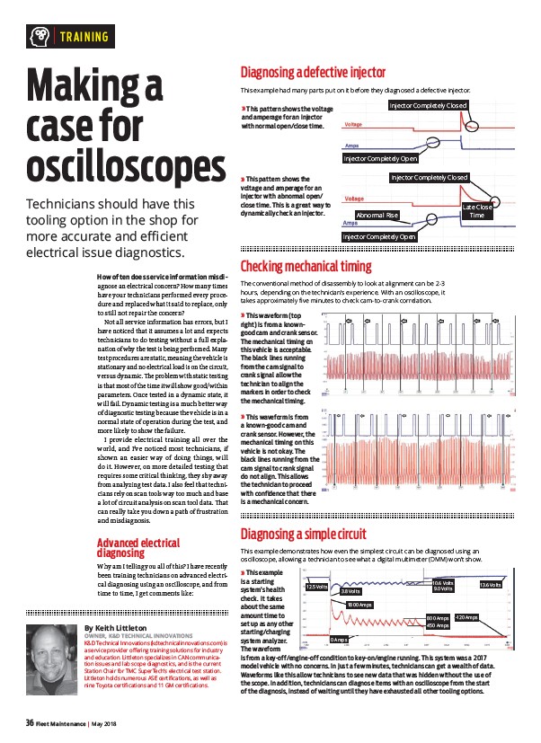
» This pattern shows the voltage
and amperage for an injector
with normal open/close time.
» This pattern shows the
voltage and amperage for an
injector with abnormal open/
close time. This is a great way to
dynamically check an injector.
» This waveform is from
a known-good cam and
crank sensor. However, the
mechanical timing on this
vehicle is not okay. The
black lines running from the
cam signal to crank signal
do not align. This allows
the technician to proceed
with confidence that there
is a mechanical concern.
Injector Completely Closed
Injector Completely Open
Injector Completely Closed
Abnormal Rise
Injector Completely Open
Late Close
Time
» This example
is a starting
system’s health
check. It takes
about the same
amount time to
set up as any other
starting/charging
system analyzer.
The waveform
is from a key-off/engine-off condition to key-on/engine running. This system was a 2017
model vehicle with no concerns. In just a few minutes, technicians can get a wealth of data.
Waveforms like this allow technicians to see new data that was hidden without the use of
the scope. In addition, technicians can diagnose items with an oscilloscope from the start
of the diagnosis, instead of waiting until they have exhausted all other tooling options.
How often does service information misdiagnose
an electrical concern? How many times
have your technicians performed every procedure
and replaced what it said to replace, only
to still not repair the concern?
Not all service information has errors, but I
have noticed that it assumes a lot and expects
technicians to do testing without a full explanation
of why the test is being performed. Many
test procedures are static, meaning the vehicle is
stationary and no electrical load is on the circuit,
versus dynamic. Th e problem with static testing
is that most of the time it will show good/within
parameters. Once tested in a dynamic state, it
will fail. Dynamic testing is a much better way
of diagnostic testing because the vehicle is in a
normal state of operation during the test, and
more likely to show the failure.
I provide electrical training all over the
world, and I’ve noticed most technicians, if
shown an easier way of doing things, will
do it. However, on more detailed testing that
requires some critical thinking, they shy away
from analyzing test data. I also feel that technicians
rely on scan tools way too much and base
a lot of circuit analysis on scan tool data. Th at
can really take you down a path of frustration
and misdiagnosis.
Advanced electrical
diagnosing
Why am I telling you all of this? I have recently
been training technicians on advanced electrical
diagnosing using an oscilloscope, and from
time to time, I get comments like:
By Keith Littleton
OWNER, K&D TECHNICAL INNOVATIONS
K&D Technical Innovations (kdtechnicalinnovations.com) is
a service provider offering training solutions for industry
and education. Littleton specializes in CAN communication
issues and lab scope diagnostics, and is the current
Station Chair for TMC SuperTech’s electrical test station.
Littleton holds numerous ASE certifications, as well as
nine Toyota certifications and 11 GM certifications.
Diagnosing a defective injector
This example had many parts put on it before they diagnosed a defective injector.
Checking mechanical timing
The conventional method of disassembly to look at alignment can be 2-3
hours, depending on the technician’s experience. With an oscilloscope, it
takes approximately five minutes to check cam-to-crank correlation.
» This waveform (top
right) is from a knowngood
cam and crank sensor.
The mechanical timing on
this vehicle is acceptable.
The black lines running
from the cam signal to
crank signal allow the
technician to align the
markers in order to check
the mechanical timing.
Diagnosing a simple circuit
This example demonstrates how even the simplest circuit can be diagnosed using an
oscilloscope, allowing a technician to see what a digital multimeter (DMM) won’t show.
12.5 Volts
3.8 Volts
10.6 Volts
9.0 Volts
13.6 Volts
800 Amps
450 Amps
-120 Amps
1800 Amps
0 Amps
/kdtechnicalinnovations.com